James Digital
Test
Hammers
Digital hammers
for the quick and easy determination of the strength of concrete.
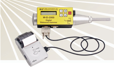
James Instruments™ digital test
hammers are an advanced, completely automated system for estimating
concrete compressive strength. Its calculation, memory and recording
functions allow for quick, easy and accurate test results.
Discard values for multiple test
results can be set; the mean, median and compressive strength can also
be calculated. The addition of modern microprocessor technology allows
the data to be stored, printed and transferred to a personal computer
for further analysis, or inclusion in your reports.
The unit comes with an integrated
alpha “ numeric digital display, and control panel. You can switch
between standard or metric units.
The field printer mounts on the
belt for ease of use.
USB Connection to a personal computer is via the USB interface.
Digital Model
W-D-2000
Automatic calculation of
mean rebound number, compressive strength and more; Field Printer, PC
connection and software for downloading
.
Digital Model
W-D-1500
Automatic calculation of
mean rebound number, compressive strength and more; Application: Rapid
estimate of concrete strength
.
ASTM
C-805
|
USA
|
BS-1881-202
|
Grt.
Brit.
|
ISO/DIS
8045
|
Intl.
|
EN
12 504-2
|
Europe
|
ENV
206
|
Europe
|
NFP
18-417
|
France
|
B
15-225
|
Belgium
|
JGJ/T
23-2001
|
China
|
JJG
817-1993
|
China
|
Specifications
Display:
|
2x16 Trans “ reflective
|
Construction:
|
All
Aluminum for rugged construction environment
|
Operating
Temperature:
|
0° to 50° C (32° to 122° F)
|
Batteries:
|
2 ˜AA™
|
Ap. Size:
|
100mm x
100mm x 270mm ( 4 x 4 x 10 )
|
Ap. Weight:
|
1.6 Kg ( 3.5 lbs.)
|
Printer
Size:
|
64mm x
49mm x 31mm
( 2.5 x 1.9 x 1.2 )
|
Weight:
|
up to
0.270 kg ( 0.6 lbs ) with paper
|
Battery:
|
Internal
Lithium ion with 1 yr. approximate life
|
Charger:
|
100VAC “
240VAC 5 VDC 3.0A
|
Operating
Temperature:
|
0° to
50° C (32° to 122° F)
|
Software
|
Windows
PC Compatible / USB interface required
|
Impact Energy
|
2.2 Nm
|
Chapter 1:
GENERAL DESCRIPTION
The concrete rebound hammer is an
instrument which is easy to use, for quick and approximate measurement
of the resistance to pressure of manufactured concrete products.
The
principles on which it works are based on the rebound impact of a
hammer on a piston which rests against the surface of the concrete
under test: the greater resistance of the
concrete, the greater the rebound impact.
By
reading this rebound impact on a scale and relating it to curves on
graphs supplied with the instrument, the resistance to compression in
MPa or PSI can be found. The test
hammer may be used for nondestructive control on cement during the
normal construction of factories and bridges.
The test makes it possible to learn
the strength of impact, which depends on the resistance of the
agglomerate in the absence of large inert lumps or clusters of sand or
gravel.
From the force of the impact the
resistance of the agglomerate surface can be deduced and subsequently
the resistance of the concrete.
With the aid of the test hammer the
quality of the concrete in every part of a construction can quickly be
examined, and in this time the hardening of the various castings can be
followed.
Chapter 2:
INSTRUCTIONS FOR USE
1.
Having taken the test
hammer from its case, gently push the piston inwards pressing it
against a surface. The piston will release itself from its catch and
emerge from the body of the device which will then be ready for testing.
2.
Press the piston against
the surface of the concrete to be tested, ho
lding the device perpendicular to the surface. Gradually apply
increasing pressure until the mass impact is released. Keep the device
firmly pressed against the surface being tested and look at the rebound
reading on the scale.
Do not touch the
side button while
pressing on the
piston.
On
removing the device from the surface being tested, the piston once more
emerges completely from the device which is immediately ready for a
second test.
3.
(Note: If it is difficult to see the
reading under the conditions specified in
Step 2) PRESS THE SIDE BUTTON ONLY AFTER
IMPACT
and
remove the device in order to read the scale.
4.
If the button is used, as
in the
case above, the piston remains inside
the device when it is removed from the surface being tested. In such
cases, in order to prepare the test hammer for further tests, activate
the hammer by the method indicated in Step 1. The position of the device when
the piston has withdrawn inside is also the position used for packing
away the device in its case.
5.
The «H» values of rebound
have been defined in such a way that they can be converted, by means of
diagrams whi
ch
are provided with the device;
into terms of resistance to
compression for tests carried out o
n the cylinder or on the cube. In each diagram, 5 different curves
have
been
reproduced, which take into acco
unt the angle of the instrument. Thus a hammer is also suitable for tests on floors, ceilings and any surfaces which are at a slope to the horizontal plane.
However, when carrying out tests on non-vertical surfaces,and hence not
holding the instrument horizontally;
it is essential to take into
account the factor of gravity acting upon the impact shock. The four
supplementary curves
on
the
graph
take into account precisely this.
For example, for a test
carried out in a floor, hence with the instrument in a vertical,
downward position (a = -90°), which gives a reading of «H» 35, we can
obtain, by means of the diagram a resistance to compression on a cube
of 36.96
MPa (5359 PSI). Similarly, the same
reading of «H» 35 would indicate resistance of 31.49
MPa (4566 PSI) if the instrument were
horizontal and the test were carried out against a vertical wall (a =
0°); and a resistance of 24.61
MPa (3568 PSI) would be obtained with
the instrument perpendicular and facing upwards, in a test being
carried out against a ceiling (a = +90°).

The curves are
valid for compact cements made with Portland cement, with sand and
gravel resistant materials. The cement must be 14 to 56 days old, with
a smooth, dry surface.
6.
The tests must be carried
out on smooth and uniform surface obtained from castings. Avoid uneven
and porous surfaces, lumps of gravel and joints in the concrete. Tests
on thin sections or zones less 10 cm, wide require particular care in
the interpretation of the results, because of the distortion due to the
elasticity of the section. If possible, the back of the section should
be held stiff by some means.
7.
Take care to remove any
materials or paint covering the concrete. If the surface is rough,
smooth it down with the rubbing stone provided with the device.
8.
It is advisable to take 15
readings in order to obtain a reliable «H» value. For each reading
change, the spot being tested by 2 or 3 cm. The «H» value can be
considered reliable if 10 to 15 readings are not further from the
average than the amount specified below:
«H» value
|
15
|
30
|
45
|
Discard
reading +/-
|
2,5
|
3,0
|
3,5
|
9.
The value of «H» to be
introduced into the graphs will be obtainable from the average of the
10 best readings.
10.
The conversion diagrams
have been derived from experiments on sample of cements left in the air
to age, from between 7 to 90 days, under normal conditions. Experience
has shown that such diagrams are not applicable in the following cases:
a.
When there are elements of
stone or cement products which differ from normal. In such as cases it
is possible to obtain new curves by experimentation.
b.
Concrete with soft
aggregates such as pumice or shale give too low a value of resistance
to compression. Also in this case, it is possible to obtain new curves
by experimentation.
c.
In hard-mix cements
or cements which are not
properly compacted
, internal leaks often occur. In
such case, the results may not correspond correctly to the calibration
curves.
d.
Very old and hard cements
have a surface which is harder than the interior and they give rebound
impact readings which are higher than they should be.
e.
New cements with damp
surface give lower rebound impact readings than they should.
f.
Frozen cements do not give
reliable results.
11.
The device does not require
special maintenance. Avoid letting dust collect in the piston and
penetrating inside the device.
Also, BEWARE of the piston and hammer becoming dirty from oil or dust from the contact surface, as this could create errors in the
rebound impact.
Digital
and manual
schmidt concrete test
hammers for quick and easy determination of concrete compressive
strength. Available in 'N' and 'L' type.
Q. Unit gives
low or high readings
?
A. Unscrew cap on top of unit, there
is a screw in the cap. Adjust the screw up or down and check reading
against test anvil.
Q. Unit will not
fire when depressed
?
A. Make sure cap screw is in the
proper position. Check to make sure trigger spring is present. Check
for plunger spring in tip
Q. My first reading
was very low, but the readings after that are consistent
?
A. Disengage hammer and let it sit
before taking your first reading.
Q. How many
readings should I take in one particular area?
A. You
should take 10 readings, if you have any large deviation, exclude them
and take additional readings.